
Aerodynamic Test of AGARD-B Model at Mach 10 in Arc-heated High-Enthalpy Wind Tunnel
-
摘要:
高超声速设备的试验能力对高超声速技术的发展至关重要,目前受制于加热器技术,常规高超声速风洞能够模拟的最高Mach数不超过10。电弧加热器是高焓风洞的重要设备,将电弧加热高焓风洞用于常规气动力试验,为提高试验模拟Mach数开辟了新的方向。介绍了中国航天空气动力技术研究院1.2 m电弧加热高焓风洞进行的AGARD-B标模试验,通过多次标模测力试验结果的标准差,检验了风洞试验数据的重复性和流场稳定性,通过和国内外已有风洞试验数据的对比分析,检验了风洞试验数据的准确性,为后续该电弧加热高焓风洞承接Mach数10的气动力试验提供强有力的技术支撑。
Abstract:The test capacity of hypersonic equipment is crucial to the development of hypersonic technology. However, the maximum Mach number simulated by conventional hypersonic wind tunnel is less than 10 currently due to the insufficient heater capacity. Considering the outstanding performance of arc heater in high-enthalpy wind tunnel, applying arc-heated high-enthalpy wind tunnel for conventional aerodynamic tests makes a breakthrough for increasing test Mach numbers. This paper presented the test of AGARD-B calibration model carried out in the arc-heated high-enthalpy wind tunnel of the China Academy of Aerospace Aerodynamics. The standard deviation of multiple repeated aerodynamic test results verified the self-consistency of test data and proved the stability of flow field. Accuracy of the test data was also certified through comparison and analysis with existing data from both foreign and domestic wind tunnels. This test demonstrated that the arc-heated high-enthalpy wind tunnel is fully capable of conducting aerodynamic tests at Mach 10.
-
Keywords:
- arc heater /
- hypersonic wind tunnel /
- Ma=10 /
- AGARD-B calibration model
-
引言
高超声速飞行器是国家空天事业战略性重大发展方向之一,未来高超声速飞行器将向更远的航程、更快的速度方向发展,不断突破飞行速度边界。高超声速飞行器性能的不断提高,需要高Mach数、高温、大尺寸、长时间的风洞设备作为研制支撑设备[1-2]。目前国内用于研究气动力和力矩等气动基础问题的连续型高超声速风洞最高Mach数达不到10,因此,亟须在提升连续式高超声速风洞Mach数方面进行研制,确保后续型号试验的需求得到满足。
高Mach数模拟能力的瓶颈主要是加热器技术。电弧加热器具有总温高、加热速度快、试验时间长的特点,是高焓风洞获得高焓流场的重要设备。近些年,国内外已有利用电弧加热器作为高超声速风洞加热源来设计的风洞设备或验证平台,典型的包括俄罗斯中央流体力学研究所(TsAGI)风洞T-117[3]、美国NASA的AHSTF(Arc-Heated Scramjet Test Facility)[4]和AEDC-H1[5]。T-117最高模拟Mach数可达18.6,进行过“暴风雪号”的测力试验,AHSTF和AEDC-H1都为了改善流场的均匀性对设备进行了改造。由此,电弧加热风洞对实现更高Mach数具有明朗的应用前景,如果能够解决均匀性和组分污染问题,将有效弥补常规高超声速风洞加热器能力不足的缺陷。2023年,林键等[6]针对中国航天空气动力技术研究院电弧加热高焓风洞开展研究,通过可调谐半导体激光吸收光谱(tunable diode laser absorption spectroscopy,TDLAS)流场诊断技术,对喷管出口NO浓度进行定量测量,建立电弧加热高焓风洞驻室参数计算方法;通过优化前室设计方法,并对流场进行细致校核,结果显示获得了均匀的流场,均匀区内的流场指标达到国军标要求。
在正式承接型号任务前,标模试验是检验一座新风洞必不可少的关键步骤。在风洞建成运行初期,风洞标模试验有特别重要的现实意义,可以考核风洞流场品质、测量仪器设备(如天平、传感器)精准度,以及验证试验技术和方法等整个系统的可行性,以评估新风洞气动力试验的准度和可信度[7-10]。高超声速风洞通常采用HSCM系列标模,包括AGARD HB-2标模、半锥角θc=10°尖锥标模、半锥角θc=9°钝锥标模及AGARD-B标模。针对HSCM系列标模的风洞气动力数据,国内外很多高超声速风洞早期做过大量的试验研究[11-16]。中国航天空气动力技术研究院张婷婷汇总了近年高超声速风洞HSCM系列标模试验的结果,给出了Ma=5~8范围内系统、全面、详实、可靠的试验数据[17]。
本文介绍了中国航天空气动力技术研究院1.2 m电弧加热高焓风洞AGARD-B标模试验,通过多次标模测力试验结果的标准差检验了风洞试验数据的重复性和流场稳定性,通过和已有国内外风洞试验数据的对比分析检验了风洞试验数据的准确性,为后续该电弧加热高焓风洞承接Mach数10的气动力试验提供强有力的技术支撑。
1. 试验模型
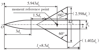
AGARD-B标模的几何外形见图 1,是一个带双三角翼的尖顶圆柱组合体,其流场的典型意义体现在翼体间复杂的气动干扰,以及激波诱导旋涡分离对气动特性产生明显的非线性效应。该标模试验研究对常见的翼体组合体气动布局外形有极其典型的现实意义。机头外形曲线(圆弧半径r与轴向坐标x关系)为
r=x3[1−19(xdb)2+154(xdb)3] 其中,db代表模型底部直径。本试验模型底部直径0.06 m,长度0.51 m,参考量的选取参照国军标《高超声速风洞气动力试验方法》(GJB 4399—2002),参考面积取模型机翼面积Sr=0.024 941 m2,力矩参考长度取机翼平均气动弦长Lr1=0.138 54 m,压心系数无因次参考长度取模型底部直径Lr2=0.06 m,力矩参考点取模型轴向上距头部顶点0.356 58 m。具体的试验参数参考文献[6]。
2. 试验数据处理
关于数据处理,作如下几点说明:
1) 假定气流从风洞前室经喷管到试验段为等熵过程,把前室的总压、总温作为自由流的总压(P0)、总温(T0)。鉴于来流总温高达950 K,完全气体方程已不适用,高温对气体的特性产生了较大的影响,所以采用热完全气体模型推导计算[18]。
2) 模型由于上下表面对称,故可对气动力数据(CN,Cmz)根据最小二乘法做过零处理。在攻角α=0°时,采用Xcp=−∂Cmα∂CNα⋅Lr1Lr2计算压心。
3) 在同一状态下进行7次重复试验,取对应点数据的平均值作为该状态下具代表性的最终结果,取对应点数据的标准差作为测量精度的结果。
3. 测力数据分析
3.1 试验精度分析
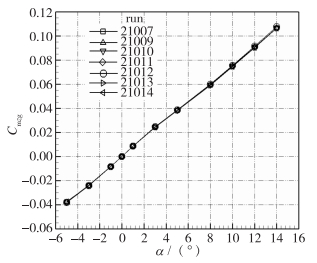
针对AGARD-B标模模型进行7次重复试验,这7次试验均在基准状态下完成。图 2~4分别给出了7次重复试验的法向力系数CN、轴向力系数CA、对参考点俯仰力矩系数Cmzg随攻角的变化曲线,曲线高度重合表明试验的重复性很好,车次21012轴向力系数CA较其他车次的系数略高,是调试总压偏低从而Reynolds数小造成的偏差。表 1列示了这7次重复性试验的测量结果,包括不同攻角下的法向力系数CN、轴向力系数CA、对参考点的俯仰力矩系数Cmzg。表 2中给出了攻角对应气动力参数的7次数据的标准差,即精度,其计算的方法为
σ=√n∑i=1(xi−ˉx)2n−1 表 1 AGARD-B标模Ma∞=10.28重复性试验测力结果Table 1. Aerodynamic test data of AGARD-B calibration model in repetitive testsα/(°) CN 21007 21009 21010 21011 21012 21013 21014 -5 -0.065 30 -0.065 45 -0.065 29 -0.065 22 -0.066 21 -0.065 27 -0.064 74 -3 -0.038 32 -0.038 70 -0.038 40 -0.038 22 -0.038 93 -0.038 50 -0.038 36 -1 -0.012 63 -0.012 83 -0.012 68 -0.012 63 -0.012 82 -0.012 63 -0.012 64 0 -0.000 05 0.000 06 0.000 05 0.000 04 0.000 05 -0.000 07 0.000 05 1 0.012 67 0.012 76 0.012 63 0.012 60 0.012 77 0.012 70 0.012 59 3 0.038 10 0.038 43 0.038 28 0.037 94 0.038 62 0.038 21 0.037 84 5 0.064 42 0.064 98 0.064 74 0.064 58 0.065 31 0.064 51 0.064 79 8 0.110 37 0.111 26 0.110 71 0.110 32 0.111 91 0.110 42 0.110 65 10 0.146 84 0.147 72 0.147 60 0.147 38 0.149 01 0.146 48 0.146 39 12 0.189 20 0.189 96 0.189 52 0.189 89 0.191 57 0.188 45 0.188 28 14 0.237 93 0.239 53 0.239 23 0.239 35 0.242 00 0.237 96 0.238 16 α/(°) CA 21007 21009 21010 21011 21012 21013 21014 -5 0.031 41 0.031 35 0.031 16 0.031 21 0.032 00 0.031 20 0.030 90 -3 0.030 61 0.030 38 0.030 23 0.030 17 0.031 15 0.030 37 0.030 18 -1 0.030 27 0.029 95 0.029 84 0.029 86 0.030 64 0.029 93 0.029 75 0 0.030 30 0.030 00 0.029 97 0.029 92 0.030 79 0.030 05 0.029 85 1 0.030 38 0.030 23 0.030 17 0.030 17 0.030 95 0.030 18 0.030 05 3 0.030 85 0.030 71 0.030 60 0.030 61 0.031 36 0.030 65 0.030 38 5 0.031 87 0.031 57 0.031 40 0.031 56 0.032 36 0.031 61 0.031 26 8 0.034 39 0.034 19 0.033 97 0.034 16 0.034 95 0.034 12 0.033 83 10 0.036 65 0.036 23 0.036 19 0.036 21 0.037 35 0.036 24 0.035 96 12 0.038 98 0.038 72 0.038 56 0.038 58 0.039 77 0.038 61 0.038 49 14 0.041 56 0.041 48 0.041 42 0.041 36 0.042 59 0.041 43 0.041 40 α/(°) Cmzg 21007 21009 21010 21011 21012 21013 21014 -5 -0.037 65 -0.037 96 -0.037 78 -0.037 88 -0.038 31 -0.037 83 -0.037 60 -3 -0.023 83 -0.024 29 -0.024 01 -0.024 04 -0.024 38 -0.024 25 -0.024 15 -1 -0.008 33 -0.008 51 -0.008 46 -0.008 47 -0.008 49 -0.008 43 -0.008 53 0 -0.000 10 -0.000 03 -0.000 07 -0.000 04 -0.000 07 -0.000 07 0.000 02 1 0.008 42 0.008 54 0.008 53 0.008 51 0.008 56 0.008 50 0.008 51 3 0.024 25 0.024 58 0.024 56 0.024 32 0.024 55 0.024 28 0.024 21 5 0.038 17 0.038 36 0.038 33 0.038 19 0.038 51 0.038 08 0.038 61 8 0.059 11 0.059 52 0.059 35 0.059 06 0.059 83 0.058 95 0.059 28 10 0.074 83 0.075 18 0.075 04 0.074 86 0.075 51 0.074 42 0.074 48 12 0.090 79 0.090 83 0.090 58 0.090 59 0.091 47 0.090 19 0.090 19 14 0.106 62 0.106 55 0.106 61 0.106 53 0.107 63 0.106 30 0.106 37 表 2 试验气动系数精度Table 2. Test accuracy of aerodynamic coefficientsα/(°) σCN σCA σCZ σCmx σCmyg σCmzg -5 0.000 44 0.000 34 0.000 36 0.000 02 0.000 31 0.000 26 -3 0.000 25 0.000 35 0.000 10 0.000 02 0.000 11 0.000 22 -1 0.000 09 0.000 31 0.000 15 0.000 03 0.000 09 0.000 09 0 0.000 05 0.000 33 0.000 11 0.000 03 0.000 11 0.000 00 1 0.000 07 0.000 30 0.000 11 0.000 03 0.000 11 0.000 05 3 0.000 27 0.000 31 0.000 08 0.000 03 0.000 10 0.000 17 5 0.000 31 0.000 36 0.000 08 0.000 02 0.000 08 0.000 17 8 0.000 58 0.000 36 0.000 10 0.000 02 0.000 06 0.000 30 10 0.000 90 0.000 46 0.000 14 0.000 01 0.000 09 0.000 38 12 0.001 10 0.000 45 0.000 12 0.000 02 0.000 09 0.000 45 14 0.001 43 0.000 44 0.000 07 0.000 02 0.000 06 0.000 45 其中,xi是某一参数x的第i次测量结果,n是总测量次数,x是n次测量的平均值。
从表 2中可以看出,经过7次重复试验后得到的法向力系数标准差最高为0.001 43,轴向力系数的标准差最高为0.000 46,对质心的俯仰力矩系数标准差最高为0.000 45,均达到了国军标中针对AGARD HB-2标模所提供的精度指标(指标分别为0.004 5,0.003 1和0.004 6)。
3.2 试验数据准确性分析
从超声速到高超声速,国内外诸多风洞都对AGARD-B标模进行过大量的测力试验。
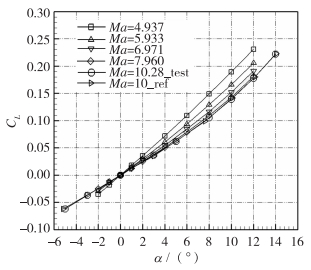
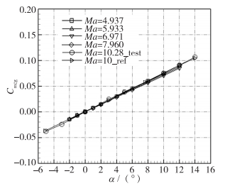
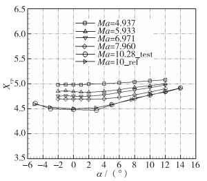
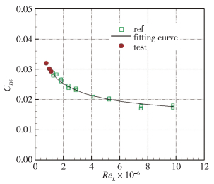
图 5~8给出了1.2 m电弧加热高焓风洞Ma=10.28下AGARD-B标模升力CL、前体阻力CDF、俯仰力矩Cmzg、压力中心位置Xcp随α的变化曲线,一同给出的还有0.5 m高超声速风洞Mach数5~8范围内AGARD-B标模的试验结果和Tunnel C风洞Ma=10 AGARD-B标模的试验结果。整体来看,Ma=10.28时,与0.5 m高超声速风洞的低Mach数数据衔接合理,随着Mach数的增加,升力减小,压心前移。与Tunnel C风洞Ma=10的数据比较:升力CL相差小于3%,但是1.2 m电弧加热高焓风洞本身校测的Mach数10.28相对于Tunnel C更大,所以理应升力更小一点;压心位置相差的量级为模型总长的千分之一,符合压心位置在高Mach数下变化平缓的规律,吻合较好。但是1.2 m电弧加热高焓风洞的前体阻力系数显著高于Tunnel C风洞,数值上是Tunnel C风洞的1.5倍,这和两座风洞的Reynolds数差异大有关。前体阻力系数CDF对Reynolds数效应更为敏感,文献[17]详细汇总了攻角α=0°时前体阻力系数CDF随Re的变化,如图 9所示,1.2 m电弧加热高焓风洞调试了3个不同Reynolds数状态进行验证,3个状态下的CDF均与拟合曲线的趋势完全吻合。这里需要解释的是,Mach数越高,底阻在总阻的占比越小,Ma=10下考虑底阻与不考虑底阻的偏差不到2%。本文还是考虑了底阻修正,但是鉴于风洞调试总压低,P0=3 MPa,来流静压约为55 Pa,所以底部压力为更低的一个值,风洞现有的传感器精度不足以准确测量底阻。为了和国外数据进行比较,底压设置为30 Pa。
![]() 图 9 α=0°前体阻力随Reynolds数的变化关系Figure 9. Forebody drag coefficient versus Reynolds number at α=0°
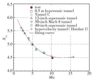
图 9 α=0°前体阻力随Reynolds数的变化关系Figure 9. Forebody drag coefficient versus Reynolds number at α=0°文献[17]比较全面地归纳了国外从超声速到高超声速诸多风洞AGARD-B标模试验数据,包括α=0°附近升力线斜率CLα、零升压力中心位置Xcp随Ma的变化,将1.2 m电弧加热高焓风洞的试验数据和国内外风洞的相比较,见图 10和图 11。可以看出,1.2 m电弧加热高焓风洞Ma=10.28的CLα试验点准确地落在国外风洞CLα~Ma拟合曲线上;Xcp试验点与Xcp~Ma曲线的变化极其一致,偏差大约为1%。
不同风洞间的系统误差存在差异,包括流场品质、天平及测试仪器的精度、模型尺度与制造偏差、支杆粗细对底部流场的干扰、模型在风洞中安装姿态的偏差等,这些因素都可能影响到气动力测量结果。尽管如此,但是1.2 m电弧加热高焓风洞Ma=10.28的试验数据点与国内外风洞试验结果在各方面吻合较好,从量值和规律上反映了该风洞AGARD-B标模气动力测量结果的一致性和衔接性。
4. 结论
本文介绍了中国航天空气动力技术研究院1.2 m电弧加热高焓风洞AGARD-B标模试验,通过多次标模测力试验结果的标准差检验了风洞试验数据的重复性和流场稳定性,通过和已有国内外风洞试验数据的对比分析检验了风洞试验数据的准确性,为后续该电弧加热高焓风洞承接Mach数10的气动力试验提供强有力的技术支撑。
-
![]()
图 9 α=0°前体阻力随Reynolds数的变化关系
Figure 9. Forebody drag coefficient versus Reynolds number at α=0°
表 1 AGARD-B标模Ma∞=10.28重复性试验测力结果
Table 1 Aerodynamic test data of AGARD-B calibration model in repetitive tests
α/(°) CN 21007 21009 21010 21011 21012 21013 21014 -5 -0.065 30 -0.065 45 -0.065 29 -0.065 22 -0.066 21 -0.065 27 -0.064 74 -3 -0.038 32 -0.038 70 -0.038 40 -0.038 22 -0.038 93 -0.038 50 -0.038 36 -1 -0.012 63 -0.012 83 -0.012 68 -0.012 63 -0.012 82 -0.012 63 -0.012 64 0 -0.000 05 0.000 06 0.000 05 0.000 04 0.000 05 -0.000 07 0.000 05 1 0.012 67 0.012 76 0.012 63 0.012 60 0.012 77 0.012 70 0.012 59 3 0.038 10 0.038 43 0.038 28 0.037 94 0.038 62 0.038 21 0.037 84 5 0.064 42 0.064 98 0.064 74 0.064 58 0.065 31 0.064 51 0.064 79 8 0.110 37 0.111 26 0.110 71 0.110 32 0.111 91 0.110 42 0.110 65 10 0.146 84 0.147 72 0.147 60 0.147 38 0.149 01 0.146 48 0.146 39 12 0.189 20 0.189 96 0.189 52 0.189 89 0.191 57 0.188 45 0.188 28 14 0.237 93 0.239 53 0.239 23 0.239 35 0.242 00 0.237 96 0.238 16 α/(°) CA 21007 21009 21010 21011 21012 21013 21014 -5 0.031 41 0.031 35 0.031 16 0.031 21 0.032 00 0.031 20 0.030 90 -3 0.030 61 0.030 38 0.030 23 0.030 17 0.031 15 0.030 37 0.030 18 -1 0.030 27 0.029 95 0.029 84 0.029 86 0.030 64 0.029 93 0.029 75 0 0.030 30 0.030 00 0.029 97 0.029 92 0.030 79 0.030 05 0.029 85 1 0.030 38 0.030 23 0.030 17 0.030 17 0.030 95 0.030 18 0.030 05 3 0.030 85 0.030 71 0.030 60 0.030 61 0.031 36 0.030 65 0.030 38 5 0.031 87 0.031 57 0.031 40 0.031 56 0.032 36 0.031 61 0.031 26 8 0.034 39 0.034 19 0.033 97 0.034 16 0.034 95 0.034 12 0.033 83 10 0.036 65 0.036 23 0.036 19 0.036 21 0.037 35 0.036 24 0.035 96 12 0.038 98 0.038 72 0.038 56 0.038 58 0.039 77 0.038 61 0.038 49 14 0.041 56 0.041 48 0.041 42 0.041 36 0.042 59 0.041 43 0.041 40 α/(°) Cmzg 21007 21009 21010 21011 21012 21013 21014 -5 -0.037 65 -0.037 96 -0.037 78 -0.037 88 -0.038 31 -0.037 83 -0.037 60 -3 -0.023 83 -0.024 29 -0.024 01 -0.024 04 -0.024 38 -0.024 25 -0.024 15 -1 -0.008 33 -0.008 51 -0.008 46 -0.008 47 -0.008 49 -0.008 43 -0.008 53 0 -0.000 10 -0.000 03 -0.000 07 -0.000 04 -0.000 07 -0.000 07 0.000 02 1 0.008 42 0.008 54 0.008 53 0.008 51 0.008 56 0.008 50 0.008 51 3 0.024 25 0.024 58 0.024 56 0.024 32 0.024 55 0.024 28 0.024 21 5 0.038 17 0.038 36 0.038 33 0.038 19 0.038 51 0.038 08 0.038 61 8 0.059 11 0.059 52 0.059 35 0.059 06 0.059 83 0.058 95 0.059 28 10 0.074 83 0.075 18 0.075 04 0.074 86 0.075 51 0.074 42 0.074 48 12 0.090 79 0.090 83 0.090 58 0.090 59 0.091 47 0.090 19 0.090 19 14 0.106 62 0.106 55 0.106 61 0.106 53 0.107 63 0.106 30 0.106 37  下载: 导出CSV
表 2 试验气动系数精度
Table 2 Test accuracy of aerodynamic coefficients
α/(°) σCN σCA σCZ σCmx σCmyg σCmzg -5 0.000 44 0.000 34 0.000 36 0.000 02 0.000 31 0.000 26 -3 0.000 25 0.000 35 0.000 10 0.000 02 0.000 11 0.000 22 -1 0.000 09 0.000 31 0.000 15 0.000 03 0.000 09 0.000 09 0 0.000 05 0.000 33 0.000 11 0.000 03 0.000 11 0.000 00 1 0.000 07 0.000 30 0.000 11 0.000 03 0.000 11 0.000 05 3 0.000 27 0.000 31 0.000 08 0.000 03 0.000 10 0.000 17 5 0.000 31 0.000 36 0.000 08 0.000 02 0.000 08 0.000 17 8 0.000 58 0.000 36 0.000 10 0.000 02 0.000 06 0.000 30 10 0.000 90 0.000 46 0.000 14 0.000 01 0.000 09 0.000 38 12 0.001 10 0.000 45 0.000 12 0.000 02 0.000 09 0.000 45 14 0.001 43 0.000 44 0.000 07 0.000 02 0.000 06 0.000 45
下载: 导出CSV
-
[1] 罗月培, 孙宗祥, 孙杭义, 等. 美国高超声速风洞试验能力发展综述[J]. 飞航导弹, 2021(6): 33-41. Luo Y P, Sun Z X, Sun H Y, et al. Overview of the development of hypersonic wind tunnel experimental capability in the USA[J]. Aerodynamic Missile Journal, 2021(6): 33-41(in Chinese).
[2] 韩洪涛, 商翔伦, 夏薇, 等. 2021年国外高超声速技术发展回顾[J]. 国际太空, 2022(4): 38-42. Han H T, Shang X L, Xia W, et al. Review on the development of hypersonic technology abroad in 2021[J]. Space International, 2022(4): 38-42(in Chinese).
[3] Boldyrev S, Brazhko V, Vaganov A, et al. T-117 TsAGI hypersonic wind tunnel[R]. 2002.
[4] Witte D W, Irby R G, Auslender A H, et al. 1998 calibration of the Mach 4.7 and Mach 6 arc-heated scramjet test facility nozzles[R]. NASA/TM-2004-213250, 2004.
[5] Bruce Ⅲ W E, Horn D D, Felderman E J, et al. Arc heater development at AEDC[R]. AIAA 1994-2591, 1994.
[6] 林键, 张婷婷, 宋华振, 等. 电弧加热高焓风洞流场诊断和驻室参数计算方法[J]. 空天技术, 2023(3): 52-59, 87. Lin J, Zhang T T, Song H Z, et al. Flow field diagnosis and chamber parameters calculation method for arc heating high-enthalpy wind tunnel[J]. Aerospace Technology, 2023(3): 52-59, 87(in Chinese).
[7] 唐志共, 许晓斌, 杨彦广, 等. 高超声速风洞气动力试验技术进展[J]. 航空学报, 2015, 36(1): 86-97. Tang Z G, Xu X B, Yang Y G, et al. Research progress on hypersonic wind tunnel aerodynamic testing techniques[J]. Acta Aeronautica et Astronautica Sinica, 2015, 36(1): 86-97(in Chinese).
[8] 战培国, 罗月培. 飞行器风洞试验标模体系研究初探[J]. 气体物理—理论与应用, 2012, 7(1): 88-92. Zhan P G, Luo Y P. Primary research on the system of standard air vehicle calibration models used in wind tunnel test[J]. Physics of Gases—Theory and Applications, 2012, 7(1): 88-92(in Chinese).
[9] 中国人民解放军总装备部. GJB 4399-2002高超声速风洞气动力试验方法[S]. 北京: 总装备部军标出版发行部, 2002. General Equipment Department of People's Liberation Army of China. GJB 4399-2002 Aerodynamic test method in hypersonic wind tunnel[S]. Beijing: General Armament Department Military Standard Publishing Department, 2002(in Chinese).
[10] 许晓斌. 常规高超声速风洞与试验技术[M]. 北京: 国防工业出版社, 2015: 8. Xu X B. Conventional hypersonic wind tunnel and test technique[M]. Beijing: National Defense Industry Press, 2015: 8(in Chinese).
[11] 陈河梧. 超声速高超声速风洞测力数据衔接性的研究[J]. 空气动力学学报, 2000, 18(3): 345-349. Chen H W. Investigation on the link-up between the aerodynamic force data measured in supersonic and hypersonic wind tunnel[J]. Acta Aerodynamica Sinica, 2000, 18(3): 345-349(in Chinese).
[12] 陈河梧. 高超声速风洞测力数据的关联研究[J]. 流体力学实验与测量, 2002, 16(3): 14-18, 25. Chen H W. Correlation study on data of force-measuring test in hypersonic wind tunnel[J]. Experiments and Measurements in Fluid Mechanic, 2002, 16(3): 14-18, 25(in Chinese).
[13] Hartzuiker J P. A review of measurements on AGARD calibration model B in the Mach number range from 1.4 to 8[R]. NLR ReportMP. 200, 1961.
[14] Coats J D. Force tests of on AGARD calibration model B at Ma=2.5 to 6.0[R]. AEDC-TN-60-182, 1960.
[15] Kayser L D, Fitchc R. Force and pressure tests of an AGARD calibration model B at a Mach number of 8[R]. AEDC-TN-60-34, 1960.
[16] Matthews R K, Trimmer L L. Force and pressure tests of an AGARD calibration model B at Mach number of 10[R]. AD 430701, 1964.
[17] 张婷婷, 叶瑞, 姜维, 等. 高超声速风洞HSCM系列标准模型气动力实验数据[J]. 气体物理, 2021, 6(4): 57-65. DOI: 10.19527/j.cnki.2096-1642.0843 Zhang T T, Ye R, Jiang W, et al. Aerodynamic test data of HSCM calibration models in hypersonic wind tunnel[J]. Physics of Gases, 2021, 6(4): 57-65(in Chinese). DOI: 10.19527/j.cnki.2096-1642.0843
[18] Ames Research Staff. Equations, tables, and charts for compressible flow[R]. NACA-TR-1135, 1953.


计量
- 文章访问数: 71
- HTML全文浏览量: 9
- PDF下载量: 14


 邮件订阅
邮件订阅 RSS
RSS